Decoding Valve Symbols: A Beginner’s Guide
Decoding Valve Symbols: A Beginner’s Guide to Pneumatic Schematics
Staring at a pneumatic circuit diagram for the first time can feel a bit like trying to read ancient hieroglyphics. You see boxes, arrows, and T-shaped lines scattered everywhere, and while it looks professional, it doesn’t exactly scream “easy to understand.”
But here’s the secret: Pneumatic symbols are incredibly logical. They don’t just represent what a valve looks like; they describe exactly what the valve does.
Whether you’re a maintenance technician or a DIY enthusiast, this guide will help you crack the code.
1. The Foundation: The “Boxes” (Positions)
Every valve symbol is made up of one or more squares. These squares represent the valve’s positions.
-
- Single Box: The valve only has one state (rare for directional control).
- Two Boxes: This is a two-position valve, usually On/Off or Extend/Retract.
- Three Boxes: A three-position valve that typically includes a neutral or center position where everything stops or exhausts.
Pro Tip: In a schematic, the box with the lines connected to it represents the valve’s resting or de-energized state.

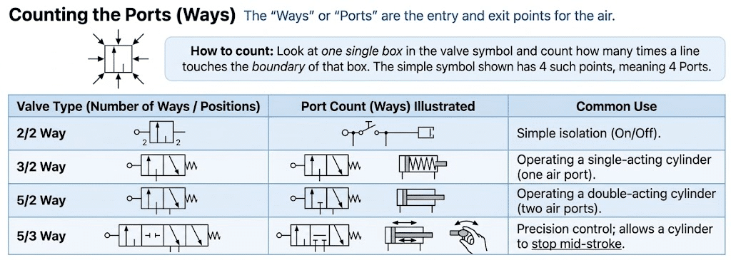
2. Counting the Ports (Ways)
The “Ways” or “Ports” are the entry and exit points for the air. To count them, look at a single box in the symbol and count how many times a line touches the boundary of that box.
| Valve Type | Common Use |
|---|---|
| 2/2 Way | Simple isolation (On/Off). |
| 3/2 Way | Operating a single-acting cylinder (one air port). |
| 5/2 Way | Operating a double-acting cylinder (two air ports). |
| 5/3 Way | Precision control; allows a cylinder to stop mid-stroke. |
3. Understanding the Arrows and Lines
The symbols inside the boxes tell you where the air is going.
- Arrows: Show the direction of air flow.
- T-Lines (Blocks): Indicate a closed port. Think of them as a dead end where no air can pass.
- Triangles: Represent the exhaust. If attached directly to the box, it indicates a vented exhaust. If slightly detached, it usually indicates a threaded exhaust port where a silencer can be installed.
4. How Is It Actuated? (The “Sides”)
The symbols attached to either side of the valve indicate how it changes from one position to another.
-
- Solenoid: Triggered by an electrical signal.
- Spring: Returns the valve to its default position when power or signal is removed.
- Push Button: Manual operation by an operator.
- Pilot: Actuated by a separate pulse of compressed air.

Putting It All Together: The 5/2 Solenoid-Spring Valve
Imagine a valve symbol with two boxes. On one side is a solenoid, and on the other is a spring.
When the solenoid is energized, it shifts the valve and directs air to extend a cylinder. When power is removed, the spring returns the valve to its default position, directing air to retract the cylinder.
Why Does This Matter?
Learning to read pneumatic symbols allows you to troubleshoot machines without taking them apart. You can follow the schematic, identify where pressure should be present, and quickly narrow down the source of a problem.
Need Help Finding the Right Pneumatic Components?
Understanding pneumatic schematics is only half the battle. Whether you’re replacing a faulty valve, sourcing a repair kit, upgrading your air preparation equipment, or building an entirely new system, having the right components is essential for reliable performance.
At Pneumatics Now, we supply the pneumatic products professionals depend on every day, including valves, cylinders, FRLs, filters, regulators, lubricators, repair kits, hose reels, air tools, fittings, tubing, and more.
Not sure which part you need? Our team can help identify components, cross-reference part numbers, and offer solutions for new installations or maintenance projects.
Contact Pneumatics Now today for assistance, pricing, and fast access to the pneumatic parts and equipment that keep your operation running.
Pneumatics Now — Your Trusted Source for Pneumatic Components, Replacement Parts, and Compressed Air Solutions.